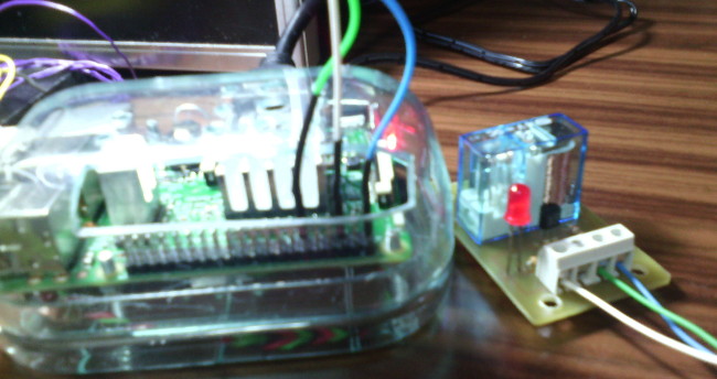
Relé controlado por la Raspberry Pi 3 con programación en Java.
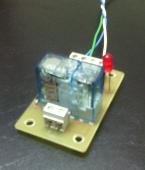
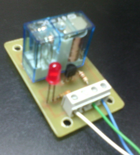
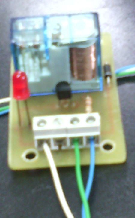
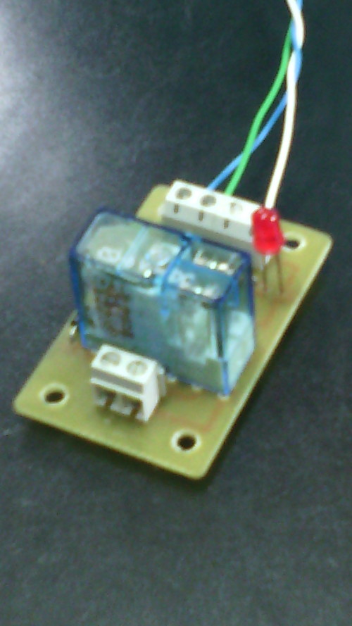
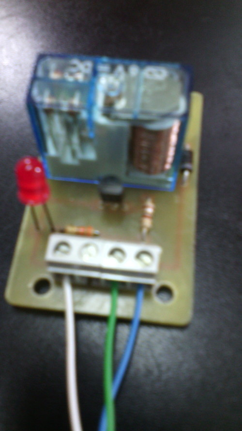
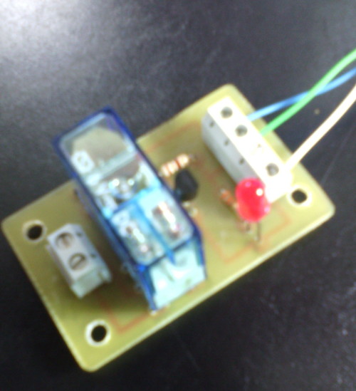
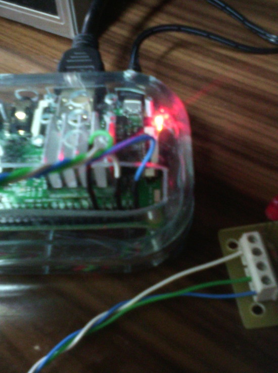
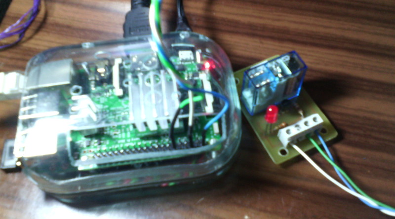
La Raspberry Pi remite la señal de activación por el pin GPIO.1 (pín físico 12, cable VERDE). Esa señal se envía a través de una resistencia de 100 Ohmios a la base del transistor NPN (C945). En el colector del transistor se ha conectado el pin físico 2 de la Raspberry Pi 3 que facilita 5V DC (cable azul). Al recibir señal por el GPIO.1, el transitor conmuta y hace llegar los 5V a la bobina del relé. También se ha acoplado a la llegada de la señal GPIO.1 un led con su correspondiente resistencia limitadora (330 Ohms) de forma que al recibir la señal de activación de la Raspberry, se activa el relé y el led. La masa (0V) está conectada al pin físico 6 (cable BLANCO).
El programa Java lo he obtenido de "The Pi4J Project - Java I/O library for the Raspberry Pi": http://pi4j.com/
Es necesario instalar las clases que utiliza este projecto según se indica en la página: http://pi4j.com/install.html
Orden para compilar el programa...
javac -classpath .:classes:/opt/pi4j/lib/'*' ControlGpioExample.java
Orden para ejecutar el programa...
java -classpath .:classes:/opt/pi4j/lib/'*' ControlGpioExample
Componentes y placa de circuito...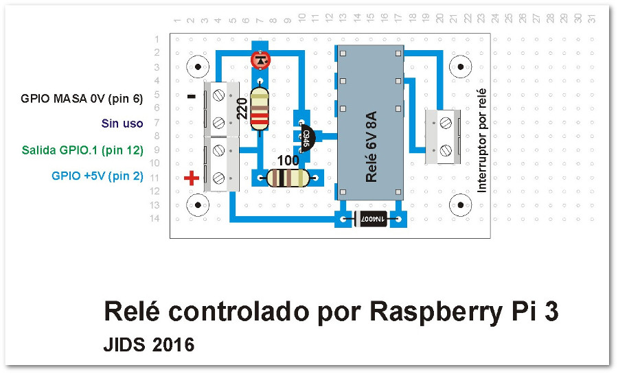
Componentes...
Pistas (tamaño del circuito impreso: 57mm x 36mm)
Cableado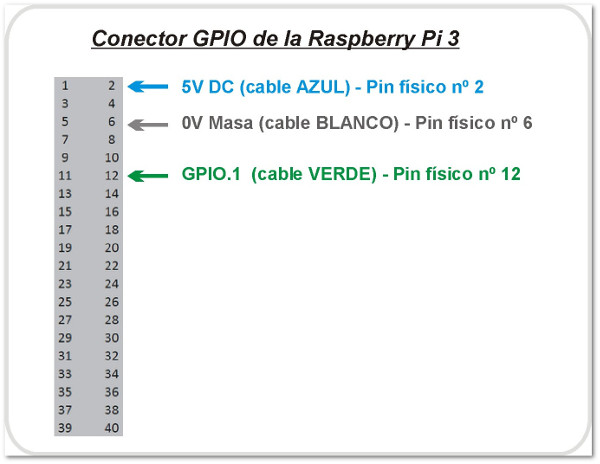
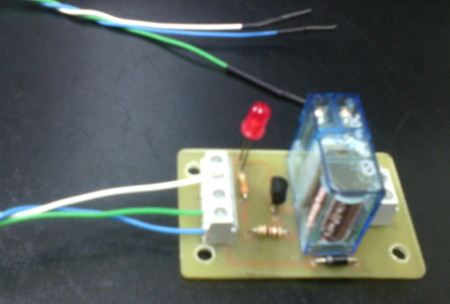
Imágenes del montaje
PCB - Pistas de cobre
PCB - Lado fibra de vídrio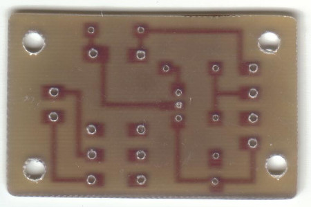
Programa en Java que activa y desactiva varias veces el relé con diferentes tiempos de activación para hacer pruebas del funcionamiento.
// START SNIPPET: control-gpio-snippet

/*
 * #%L
 * **********************************************************************
 * ORGANIZATION  :  Pi4J
 * PROJECT       :  Pi4J :: Java Examples
 * FILENAME      :  ControlGpioExample.java
 *
 * This file is part of the Pi4J project. More information about
 * this project can be found here:  http://www.pi4j.com/
 * **********************************************************************
 * %%
 * Copyright (C) 2012 - 2016 Pi4J
 * %%
 * This program is free software: you can redistribute it and/or modify
 * it under the terms of the GNU Lesser General Public License as
 * published by the Free Software Foundation, either version 3 of the
 * License, or (at your option) any later version.
 *
 * This program is distributed in the hope that it will be useful,
 * but WITHOUT ANY WARRANTY; without even the implied warranty of
 * MERCHANTABILITY or FITNESS FOR A PARTICULAR PURPOSE.  See the
 * GNU General Lesser Public License for more details.
 *
 * You should have received a copy of the GNU General Lesser Public
 * License along with this program.  If not, see
 * <http://www.gnu.org/licenses/lgpl-3.0.html>.
 * #L%
 */

import com.pi4j.io.gpio.GpioController;
import com.pi4j.io.gpio.GpioFactory;
import com.pi4j.io.gpio.GpioPinDigitalOutput;
import com.pi4j.io.gpio.PinState;
import com.pi4j.io.gpio.RaspiPin;

/**
 * This example code demonstrates how to perform simple state
 * control of a GPIO pin on the Raspberry Pi.
 *
 * @author Robert Savage
 */
public class ControlGpioExample {

    public static void main(String[] args) throws InterruptedException {

        System.out.println("<--Pi4J--> GPIO Control Example ... started.");

        // create gpio controller
        final GpioController gpio = GpioFactory.getInstance();

        // provision gpio pin #01 as an output pin and turn on
        final GpioPinDigitalOutput pin = gpio.provisionDigitalOutputPin(RaspiPin.GPIO_01, "MyLED", PinState.HIGH);

        // set shutdown state for this pin
        pin.setShutdownOptions(true, PinState.LOW);

        System.out.println("--> GPIO state should be: ON");

        Thread.sleep(500);

        // turn off gpio pin #01
        pin.low();
        System.out.println("--> GPIO state should be: OFF");

        Thread.sleep(300);

        // toggle the current state of gpio pin #01 (should turn on)
        pin.toggle();
        System.out.println("--> GPIO state should be: ON");

        Thread.sleep(500);

        // toggle the current state of gpio pin #01  (should turn off)
        pin.toggle();
        System.out.println("--> GPIO state should be: OFF");

        Thread.sleep(100);

        // turn on gpio pin #01 for 1 second and then off
        System.out.println("--> GPIO state should be: ON for only 1 second");
        pin.pulse(1000, true); // set second argument to 'true' use a blocking call

        // stop all GPIO activity/threads by shutting down the GPIO controller
        // (this method will forcefully shutdown all GPIO monitoring threads and scheduled tasks)
        gpio.shutdown();

        System.out.println("Exiting ControlGpioExample");
    }
}
//END SNIPPET: control-gpio-snippet
Descargar código fuente: "ControlGpioExample.java"